Valve actuator sizing starts with the valve, not the actuator. Take the valve maker’s breakaway, running and reseating torques, add a safety margin that suits the service, then choose the smallest actuator that exceeds each one at the matching point of the stroke, at minimum supply pressure. Then check that its maximum output stays below the valve’s maximum allowable stem torque.
The principle is the same for a pipeline ball valve, a butterfly valve at a water treatment works or a plug valve in a chemical plant, on air or hydraulic oil. Below are the steps, with two worked examples from our published data.
What information you need to size a valve actuator
- Valve type and size: ball (floating or trunnion mounted), butterfly or plug, with pressure class and top flange details.
- Valve torques: breakaway, running and reseating at a stated differential pressure, plus the MAST.
- Media and service: clean liquid, dry gas, slurry or viscous fluid, temperature and how often the valve moves.
- Supply pressure: minimum and maximum, measured at the actuator rather than at the compressor or pump.
- Fail-safe mode and stroke time: fail-closed, fail-open or stay put, and the opening and closing times.
Tell us the zone, gas group and temperature class, and we will confirm the certification for your exact unit.
Why the valve maker’s torque figures come first
The valve maker’s figures reflect how its seats, seals and stem behave under pressure, so they are the starting point for every actuator torque calculation; valve size alone does not tell you the torque.
Breakaway, running and reseating torque
Breakaway torque (break to open) starts the valve moving from closed and is often the highest, because the seals are in static contact. Running torque through mid-stroke is normally lower. Reseating torque (end to close) drives the valve fully home so that it seals. Some valve makers quote break, run and end torques for each direction; check each stroke against its own figures.
Torque is usually quoted at a stated pressure, often the valve’s rated pressure. Dry gas, viscous or abrasive media, long idle periods and flow effects can push it higher; on butterfly valves, flow-induced torque can peak part-way open. Unless the valve maker says its figures include a margin, assume they do not.
Maximum allowable stem torque (MAST)
MAST is the highest torque the stem can carry without permanent deformation or failure, so it caps actuator output. ISO 12490 (also published as API 6DX) sets sizing and mechanical integrity requirements for pipeline valve actuators and their mounting kits.
How to apply an actuator safety factor
An actuator safety factor covers the gap between the valve maker’s figures and real service: wear, deposits, temperature, pressure dips and idle periods. There is no universal figure; practice varies by service, end user and valve maker. One trade-press guideline, for use where the valve maker gives no factor, starts at 20% for wet or lubricating media, 30% for dry gas and 50% for viscous or abrasive media, then adds more for modulating control and for valves that move only weekly or monthly. Another notes that many users ask for 25%. Where the end user and valve maker state different factors, apply the higher one.
Our published HYLINE-K method uses 20%, as do the examples below; our engineers confirm the margin for each duty.
Check actuator torque at every point of the stroke
At minimum supply pressure, the actuator must exceed the valve’s torque plus margin at the start, middle and end of the stroke.
Rack and pinion: broadly even torque. A rack and pinion gives broadly even torque through the stroke, so one figure per supply pressure usually covers the check. It suits a wide range of quarter-turn valves and is common on smaller ones.
Scotch yoke: a U-shaped torque curve. A Scotch yoke turns piston force into a quarter turn through a slotted yoke. Its lever arm is longest at each end, so torque peaks at 0° and 90°, where breakaway and reseating happen, and dips at mid-stroke, where the valve normally moves freely. That suits larger, high-torque valves. Our guide to Scotch yoke vs rack and pinion actuators compares the two.
Worked example 1: sizing a double-acting HYLINE-K
This follows the published method for our HYLINE-K double-acting rack and pinion actuator.
- Valve torque: the valve maker’s highest torque figure is 400 Nm.
- Add the 20% margin: 400 x 1.2 = 480 Nm.
- Pick the pressure column: minimum air supply is 5 bar, so use the 5 bar column.
- Read down to the first model above 480 Nm: the AKD-140 gives 428 Nm, too little; the AKD-160 gives 665 Nm, so it is the selection.
- Check the stem: if the supply can reach 7 bar, the AKD-160 gives 931 Nm. Confirm the valve’s MAST is above this, or regulate the supply.
Air consumption for the AKD-160
The HYLINE-K formula is: Air per minute = (opening + closing air volume in litres) x (supply pressure in kPa + 101.3) / 101.3 x cycles per minute The AKD-160 uses 3.70 litres of air to open and 3.20 litres to close. At 6 bar (600 kPa), cycling once a minute: (3.70 + 3.20) x (600 + 101.3) / 101.3 x 1 = 47.8, or about 48 litres of free air per minute.
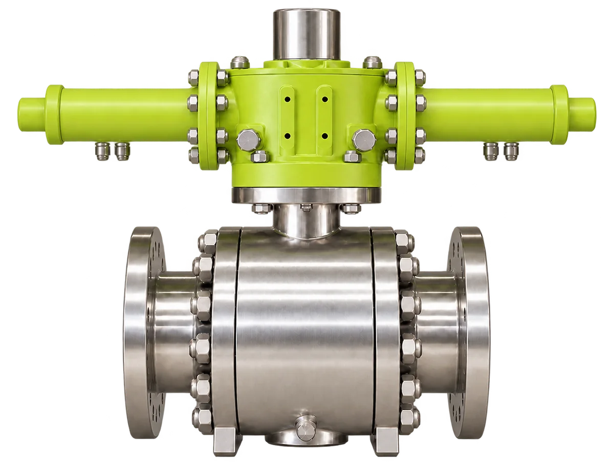
Worked example 2: a Scotch yoke HYLINE-R on a large ball valve
This example uses the published 4 bar double-acting table for the HYLINE-R Scotch yoke actuator. The ball valve needs 2,900 Nm breakaway, 1,500 Nm running and 2,700 Nm reseating, with 4 bar minimum air. The 20% margin is for illustration only; our engineers confirm the margin for each duty.
| Point in stroke | Valve torque (Nm) | Plus 20% (Nm) | E-R-T2-S-301DA at 4 bar (Nm) | Headroom (Nm) |
|---|---|---|---|---|
| Breakaway (stroke end) | 2,900 | 3,480 | 3,750 | 270 |
| Running (45°) | 1,500 | 1,800 | 2,050 | 250 |
| Reseating (stroke end) | 2,700 | 3,240 | 3,750 | 510 |
The E-R-T2-S-301DA clears all three points. The next size down, the E-R-T1-S-251DA, gives only 2,050 Nm at the ends, well short of 3,480 Nm. Mid-stroke passes, despite being the low point of the curve, because the valve needs less there. If your supply can exceed 4 bar, ask us for the torque at maximum pressure to check against the MAST. Hydraulic HYLINE-R torque depends on supply pressure, so we give figures on request.
Spring-return actuator sizing: check both strokes
The spring drives one stroke; the supply drives the other, compressing the spring.
- Spring stroke: the spring must exceed the valve’s torques in the fail direction, with margin, right to the end of its stroke, where spring force is lowest and a fail-closed valve must reseat.
- Powered stroke: use the net torque left after compressing the spring, not the double-acting figure.
- Stem check: the highest stem torque can come from the spring, so check it against the MAST too.
Our E-R-T2-S-301SRC5 fail-closed model, for example, gives 1,485 Nm spring torque at the fail position and net air torque of 2,304, 989 and 1,351 Nm at 0°, 45° and 90° at 4 bar. Because the strokes interact, send us your full valve torques for spring-return sizing. Our guide to fail-safe valve actuators explains the fail modes.
Avoid oversizing beyond the valve’s stem torque
An oversized actuator costs and weighs more, and if it delivers more than the MAST it can twist or break the stem. Check its output at maximum supply pressure, or full spring force. If it would, choose a smaller actuator with a margin agreed with the valve maker, or fit a pressure regulator with a relief valve set to protect the stem. A regulator cannot limit spring torque, and a stronger stem material can be costly.
Stroke time and compressor capacity
Pneumatic stroke time depends on swept volume and how quickly air gets in and out: supply pressure, tubing and port sizes, solenoid valve capacity and exhaust restrictions. Quick exhaust valves speed up the exhaust, and we supply them with HYLINE-R where required. Hydraulic stroke time depends mainly on the oil flow available and the cylinder’s swept volume. For reference, the HYLINE-K data sheet gives the AKD-160 2.60 s from 90° to 0° and 3.93 s from 0° to 90°; installed times will vary.
Faster is not always better: closing a valve on a liquid line too quickly can cause a damaging pressure surge (water hammer). To check compressor capacity, add up the air demand of every actuator that may move at once.
Advanced Actuators quarter-turn ranges
Our established, field-proven quarter-turn ranges already cover the vast majority of ball, butterfly and plug valve duties in oil and gas, chemical processing, water and wastewater, power generation, and offshore and marine service. Where a duty is genuinely different, we engineer around it.
- HYLINE-K: double-acting pneumatic rack and pinion in 15 sizes, 9.2 Nm to 3,509 Nm at 6 bar. It stays where it is if air is lost, so for fail-safe duty choose HYLINE-R spring-return.
- HYLINE-R: hydraulic or pneumatic Scotch yoke, double-acting or spring-return, in six sizes; double-acting pneumatic units give 1,300 Nm to 16,350 Nm at the stroke ends at 4 bar air.
The valve-type chooser on our actuator products page narrows it down.
Frequently asked questions
What safety factor should I use for valve actuator sizing?
There is no single figure, because practice varies by service, end user and valve maker. One trade-press guideline starts at 20% for wet or lubricating media, 30% for dry gas and 50% for viscous or abrasive media, adding more for modulating control or valves that rarely move. Our published HYLINE-K method uses 20%. Where specifications differ, apply the higher factor, and confirm the margin for your duty with us.
How do you do an actuator torque calculation for a quarter-turn valve?
Take the valve maker’s breakaway, running and reseating torques, add your safety margin to each, and compare the results with the actuator’s output at the matching points of the stroke at minimum supply pressure. A valve needing 400 Nm, with a 20% margin, needs an actuator giving at least 480 Nm. Then check the actuator’s maximum output against the valve’s MAST.
Why size a pneumatic actuator at minimum supply pressure?
Pneumatic actuator torque rises and falls with supply pressure, so the actuator must still exceed the valve torque when pressure at the valve is lowest. That can be well below the compressor setting because of line losses and other demand. Sizing at normal pressure risks a valve that will not open, stalls part-way or will not reseat.
Can a valve actuator be too big?
Yes. An oversized actuator costs and weighs more, and if its maximum output exceeds the valve’s maximum allowable stem torque it can twist or break the stem. Check its output at maximum supply pressure, and full spring force on spring-return units, against the MAST. A smaller actuator, or a regulator with a relief valve, keeps it within limits.
How do you size a spring-return actuator?
Check both strokes. The spring must exceed the valve’s torques in the fail direction, with margin, right to the end of its stroke, where spring force is lowest. On the powered stroke, the net torque left after compressing the spring must exceed the valve’s torques at minimum supply pressure. Because the two interact, send your valve torques to our engineers and we will size the HYLINE-R spring-return unit.
How do I calculate actuator air consumption?
Add the opening and closing air volumes in litres, multiply by (supply pressure in kPa + 101.3) / 101.3, then multiply by the cycles per minute. A HYLINE-K AKD-160 at 6 bar, cycling once a minute, needs about 48 litres of free air per minute. Add up every actuator that may move at once to check compressor capacity.
Talk to our engineers about actuator sizing
Send us the following and we will recommend a size for your valve:
- Valve type, size, pressure class and top flange details
- Breakaway, running and reseating torque and the MAST, with the differential pressure they apply to
- Media, temperature and how often the valve operates
- Minimum and maximum air or hydraulic supply pressure
- Fail-safe requirement and stroke time
- Zone, gas group and temperature class
Email sales@advanced-actuators.com, call +44 (0)1535 655151 or visit our contact page. You can also start from the HYLINE-R or HYLINE-K product page.