The difference between a linear and a rotary actuator is the motion it gives the valve. A linear actuator pushes and pulls a stem in a straight line and is rated in thrust. A rotary actuator turns a shaft and is rated in torque: a quarter-turn (90°) for ball, butterfly and plug valves, or many turns (multi-turn) for valves and penstocks driven through a threaded stem.
So start with the valve, not the actuator. Work out how it moves, size for the force it needs at the hardest point of the stroke, then choose the control mode, fail-safe position and mounting.
Linear, quarter-turn and multi-turn: the three valve motions
Linear motion: sliding-stem and rising-stem valves. In a sliding-stem control valve, such as a globe valve, a plug on a sliding stem moves straight towards or away from the seat, so the actuator pushes and pulls the stem. Gate valves, knife gate valves and penstocks (slide gates) also move in a straight line: a cylinder can push the stem directly, or a handwheel or multi-turn actuator can wind a threaded stem.
Quarter-turn rotary: ball, butterfly and plug valves, and dampers. Ball, butterfly and plug valves go from fully open to fully closed in a 90° turn, so they need a quarter-turn (part-turn) actuator. Blade dampers are similar, with blades that turn on shafts.
Multi-turn: valves and penstocks driven through a threaded stem. A multi-turn actuator rotates a stem nut or threaded stem, depending on the valve design. Relative movement between the nut and stem converts rotation into linear travel to raise or lower the gate. Gate valves and penstocks with rising or non-rising stems are typical examples.
How linear and rotary actuators produce their motion
Linear actuators: diaphragm and piston cylinders
A pneumatic diaphragm actuator works against a spring with low friction, which suits precise throttling. A piston cylinder takes higher pressures and longer strokes, so it can deliver more thrust. Hydraulic fluid provides a stiff transmission of force, but position holding also depends on the circuit, seals, valve load and controls.
Quarter-turn actuators: Scotch yoke and rack and pinion
Fluid-power quarter-turn actuators commonly turn a piston’s straight-line force into rotation:
- Scotch yoke: the piston drives a pin in a slotted yoke. A symmetrical Scotch yoke commonly gives greater torque towards the ends of its travel. Other geometries differ, so use the actual model’s torque curve.
- Rack and pinion: opposed pistons with toothed racks turn a pinion, giving broadly even torque from a compact body.
Our guide to Scotch yoke vs rack and pinion actuators compares the two.
Electric actuators: motor and worm gear
An electric actuator commonly drives a worm gear from a motor: through the stem nut or valve stem for multi-turn duty, or through a part-turn gearbox or dedicated unit for quarter-turn duty. Where the worm gearing is self-locking, it holds position when power is removed.
Matching valve types to actuator motion
A starting point; the valve maker’s data settles the choice.
| Valve type | Motion | Common actuator types | Size on |
|---|---|---|---|
| Globe and other sliding-stem control valves | Linear | Diaphragm or piston cylinder, electro-hydraulic | Thrust and stroke |
| Gate and knife gate valves | Linear or multi-turn | Cylinder on the stem, or multi-turn on a threaded stem | Thrust; torque and turns if multi-turn |
| Penstocks (slide gates) | Linear or multi-turn | Hydraulic or pneumatic cylinder, or screw-stem lift | Thrust; torque and turns if multi-turn |
| Ball, plug and butterfly valves | Quarter-turn | Scotch yoke, rack and pinion, electric worm gear | Breakaway, running and reseating torque |
| Blade dampers | Part-turn | Rotary actuator on the shaft, or cylinder with crank arm | Torque at the shaft |
Thrust versus torque: sizing linear and rotary actuators
Torque for quarter-turn valves
Valve makers often publish breakaway, running and reseating torques at a stated differential pressure. Check the actuator’s output at each of those points, not just its peak, and add a safety factor; practice varies, so agree it with the valve maker. Our guide on how to size a quarter-turn valve actuator works through examples.
Thrust for sliding-stem control valves
A sliding-stem actuator’s thrust must cover:
- Unbalanced force: process pressure acting on the unbalanced area of the plug.
- Seat load: the force pressing the plug into the seat to meet the specified leakage class.
- Packing friction: obtain the design allowance from the valve maker, including adjustment, temperature and service conditions.
- Spring force: check net powered thrust and available spring thrust throughout the travel. For a fail-closed valve, verify the available seating force against the valve maker’s requirement.
Thrust, torque and turns for gate valves
Obtain the gate valve maker’s required opening and closing thrusts for the actual differential pressure, temperature and service conditions. Gate geometry, seating forces, packing friction and pressure acting on the stem can affect the load, so a single generic formula is not sufficient for every design. For a multi-turn actuator, also check the required drive torque, thrust-bearing arrangement, number of turns and operating time.
On-off versus modulating valve actuators
On-off valves sit fully open or fully closed. They need enough force to unseat and seat, a suitable stroke time and, for emergency shutdown (ESD) duty, a dependable fail-safe action. Conventional gate valves are generally intended for isolation rather than throttling; confirm any regulating duty with the valve maker. Modulating valves hold intermediate positions on a command such as 4-20 mA. Closed-loop positioning needs a suitable control function and position feedback, which may be integrated into the actuator or provided by a separate positioner. Smooth, repeatable movement is helped by low friction and a stiff drive. Globe valves throttle well, and quarter-turn valves are modulated too, for example by a modulating rotary actuator on a water treatment butterfly valve. Check that an electric actuator is rated for modulating service.
Fail-safe options for linear and rotary actuators
- Linear: a spring-return diaphragm or piston actuator fails the valve closed (air to open) or open (air to close). Hydraulic versions can use a spring or a charged accumulator.
- Quarter-turn: spring-return Scotch yoke and rack and pinion actuators fail closed or fail open. Double-acting construction alone does not guarantee holding position after supply loss. Confirm the complete circuit, any locking arrangement and the expected valve load.
- Multi-turn electric: an actuator with self-locking gearing holds its last position. If the valve must move on power loss, add stored energy such as battery backup, or consider a fluid-power actuator.
Our article on fail-safe valve actuators explains each option and how to test it.
Mounting interfaces: ISO 5211, ISO 5210, linkages and levers
ISO 5211 sets the flange and drive dimensions, with reference torques, for attaching part-turn actuators and gearboxes to industrial valves; on control valves its use is by agreement. ISO 5210 does the same for multi-turn actuators, with reference values for torque and thrust. Use the specified editions: ISO 5211:2026 and ISO 5210:2026. Linear actuator mounting is often specific to the valve, so share the valve drawing early.
Dampers may be driven directly on the blade shaft or through a crank arm and linkage, with linkage arms tying the blades together. A crank arm changes the torque reaching the shaft through the stroke, and a fouled linkage impairs its action, so keep linkages in the maintenance plan.
Linear or rotary actuator: a short selection checklist
- Valve type and motion.
- Thrust or torque data at the real differential pressure.
- Stroke, rotation angle or number of turns.
- Supply: compressed air, hydraulic or electricity only.
- Duty: on-off, ESD or modulating, and how often the valve moves.
- Fail-safe position and stroke time.
- Mounting interface and environment, including any hazardous-area zone.
Our linear and quarter-turn actuator ranges
Our established, field-proven ranges cover the vast majority of linear and quarter-turn valve applications, with bespoke engineering where a duty is genuinely different. Our valve actuator range page starts with the valve type.
HYLINE for linear valves
HYLINE electro-hydraulic linear actuators combine electric control with hydraulic force for modulating, ESD and isolating duties on globe and other sliding-stem valves, with 100 kgf to 100,000 kgf of thrust, stroke up to 300 mm, and spring-return or accumulator fail-safe. HYLINE runs from a hydraulic ring main or, with an integrated HYFLOW 24 V DC pumping unit using a 400 W motor, as a self-contained package. Confirm the available thrust, stroke and operating time for the selected supply and actuator configuration. It serves oil and gas, power generation and remote, standalone sites.
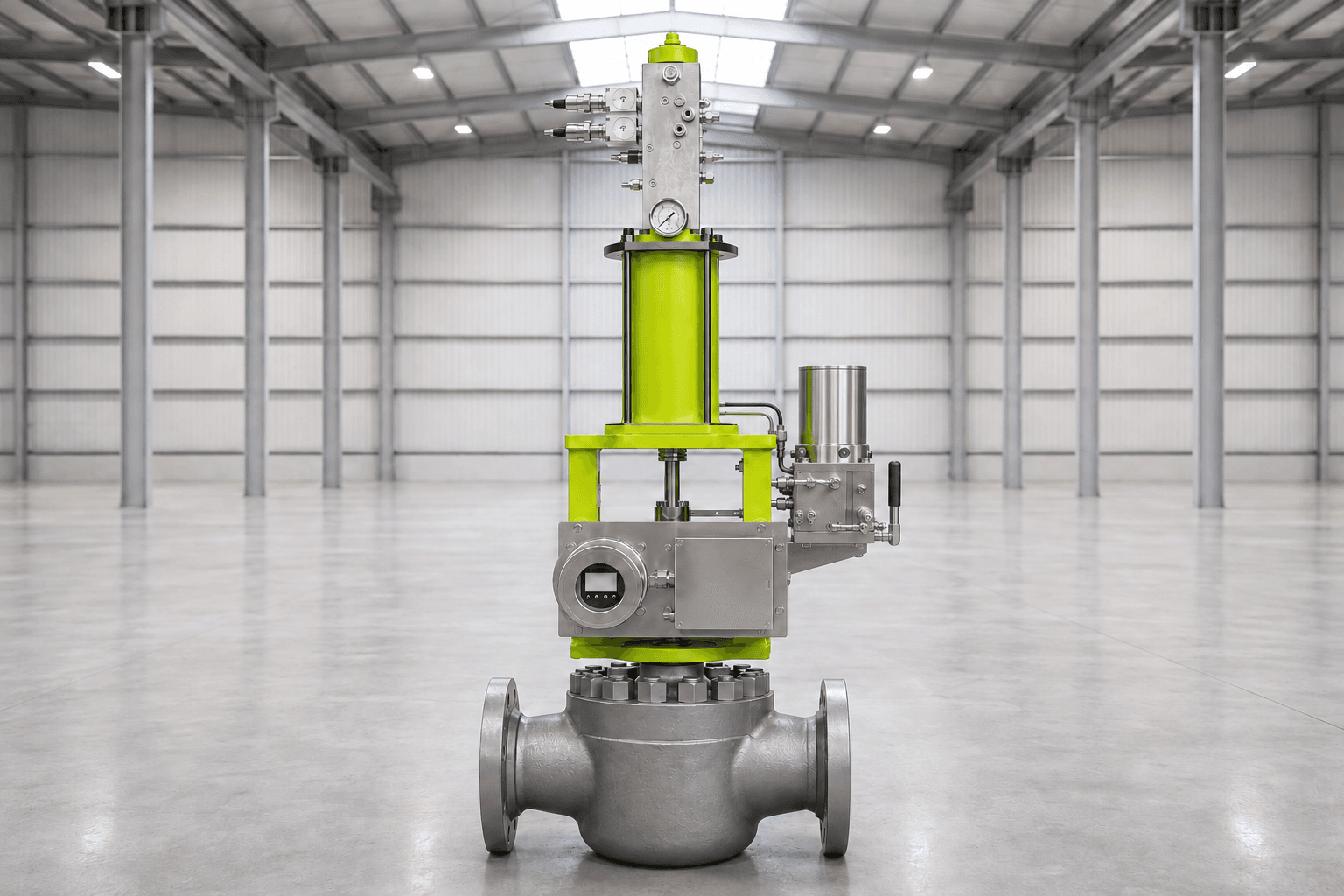
HYLINE-R and HYLINE-K for quarter-turn valves
HYLINE-R Scotch yoke actuators turn ball, plug and butterfly valves on hydraulic or pneumatic supply, double-acting or spring-return (fail-closed or fail-open), with pneumatic double-acting torque of 1,300 Nm to 16,350 Nm at the stroke ends at 4 bar. Sectors include oil and gas, chemical processing, water and wastewater, power generation, and offshore and marine.
HYLINE-K rack and pinion actuators give 9.2 Nm to 3,509 Nm at 6 bar on ISO 5211 F03 to F16 flanges. They are double-acting, so choose HYLINE-R spring-return for fail-safe duty. Where only electrical power is available, HYLINE-E electric actuators (50 Nm to 6,000 Nm) turn ball, butterfly and plug valves and dampers through 90°.
HYSTEP, rated in torque and in stroke and thrust
HYSTEP stepping actuators use electrical pulses to control pneumatic or hydraulic power and produce discrete mechanical steps for precise incremental positioning. They need a suitable fluid supply to move, while the holding mechanism maintains position under load when external power is removed. Ratings are published in both rotary and linear terms: HYSTEP CORE at 225 Nm at 4 bar and 18 steps per revolution, with stroke up to 5 in and thrust up to 4,500 kgf; HYSTEP ADVANCED at 50 to 500 Nm and 12, 18 or 36 steps per revolution, with stroke up to 10 in and thrust up to 15,000 kgf. These figures describe range capabilities, not a guarantee that every maximum is available in one configuration. HYSTEP is widely used upstream, especially on choke valves. Large gates, penstocks and dampers are engineered to suit as bespoke projects.
Frequently asked questions
What is the difference between a linear and a rotary actuator?
A linear actuator moves a valve stem in a straight line and is rated in thrust and stroke; it suits globe and other sliding-stem valves. A rotary actuator turns a shaft and is rated in torque. Quarter-turn models rotate 90° for ball, butterfly and plug valves, while multi-turn models make many turns to drive a threaded stem on gate valves and penstocks.
What is the difference between quarter-turn and multi-turn actuators?
A quarter-turn actuator rotates the valve shaft through 90° to move a ball, plug, butterfly disc or damper blade from open to closed. A multi-turn actuator rotates a stem nut or threaded stem, depending on the valve design, so the thread converts rotation into linear travel of a gate or disc. Quarter-turn units are sized on torque; multi-turn units on torque, thrust and the number of turns.
What are the main valve actuator types?
Valve actuators are grouped by motion and by power. By motion they are linear, quarter-turn or multi-turn. By power they are pneumatic, hydraulic, electro-hydraulic or electric. Pneumatic and hydraulic actuators use diaphragms or pistons, with Scotch yoke or rack and pinion mechanisms for quarter-turn duty, while electric actuators commonly use a motor driving a worm gear. The right combination depends on the valve, the supply and the duty.
Can a linear actuator operate a quarter-turn valve?
Yes. Scotch yoke and rack and pinion actuators do exactly that internally, converting the straight-line force of a piston into rotation, and a cylinder with a crank arm and linkage can turn a valve or damper shaft. What matters is the torque delivered at the shaft across the full 90°, so check it against the valve’s breakaway, running and reseating torques.
How do you size a linear valve actuator?
Use the valve maker’s required thrusts across opening and closing, including process forces, seating load and packing friction. Check the direction of each force and the available net actuator thrust throughout travel. On spring-return designs, verify both powered movement and spring-driven movement, including seating where required. Apply an agreed sizing margin and check that maximum output remains within the valve and mounting limits.
Can rotary actuators be used for modulating control?
Yes. Butterfly and other quarter-turn valves are modulated with rotary actuators in many plants, including water treatment. Closed-loop modulating control needs a suitable positioning function and position feedback, integrated into the actuator or provided by a separate positioner, with smooth, repeatable movement. Globe valves, which throttle well, take linear actuators. Electric units must be rated for modulating service, and fluid-power units benefit from low friction and a stiff drive.
Talk to our engineers about linear and rotary actuation
Not sure whether your valve needs a linear, quarter-turn or multi-turn actuator? Send the valve type and size, the torque or thrust figures, the stroke or number of turns, the supply available and the area classification to sales@advanced-actuators.com or call +44 (0)1535 655151. You can also reach us through our head office contact page, or see HYLINE linear actuators and HYLINE-R quarter-turn actuators. For hazardous areas, tell us the zone, gas group and temperature class, and we will confirm the certification for your exact unit.